
For one of my projects I need automatic measurements of TDS (Total Dissolved Solids) in a solution. There are a lot of cheap hand-held digital TDS meters available on ebay which made me give interfacing with one a shot.
After probing around on the PCB for a while I did find a signal that could be used for extracting the data. The point with the signal can be seen in figure 1, on the resistor just below the black chip-on-board.
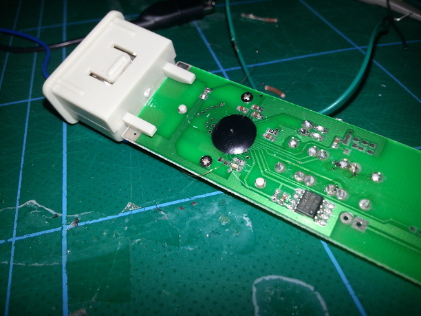
Figure 1. The magnet wire for extracting the signal is soldered to the resistor just below the chip-on-board.
The signal on this point consisted of three consecutive bursts, each about 32ms long (Figure 2.) They are all approximate triangle waves of differing frequencies. The first one is fixed at 20kHz and might be a clock reference. The second is reporting temperature where the frequency is the degrees centigrade in kHz. That is, a measured temperature of 21.3 C gives a triangle wave of 21.3 kHz. The third waveform varies in frequency with the measured TDS and is probably converted from the frequency to a PPM value by the on-board IC.
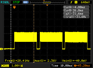
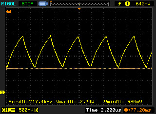
Figure 2 and 3 showing the three waveforms together and one of the waveforms magnified respectively.
Due to the waveform oscillating between about 1 and 2.4 volts a Schmitt trigger was used to yield a 3.3V square wave. I am using an Arduino Uno (atmega328) for microcontroller which runs at 5V, but 3.3V is enough to trigger the high level.
After that some simple code was written to trigger an interrupt on a falling edge, which in turn starts a 32ms long measure of frequency.
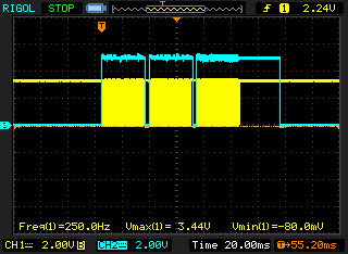
Figure 3 showing the output of the Schmitt trigger (yellow) and debug output from the Arduino showing when the frequency measurements are being done (blue).
I’m unsure about why the input on channel 2 (blue) stays high for 32ms longer on the third waveform, but it might just be an artefact of some earlier buggy code. The data I’m getting in the end is reasonable.
The input signal is attached to both pin 3 and 5 on the Arduino. Pin 3 provides the interrupt and pin 5 is for accurate frequency measurement on hardware counter.
The code is as follows:
#include <FreqCounter.h>

volatile byte triggered = 0;
volatile unsigned long trig_time = 0;
volatile unsigned long last1_trig_time = 0;
volatile unsigned long last2_trig_time = 0;
volatile byte send_data = 0;

void isr()
{
  if(!triggered)
  {
    trig_time = micros();
    triggered = 1;
  }
}

void setup()
{
  FreqCounter::f_comp = 10;
  pinMode(3, INPUT);
  pinMode(5, INPUT);
  digitalWrite(3, LOW);
  digitalWrite(5, LOW);
  attachInterrupt(1, isr, FALLING);
  Serial.begin(115200);
}

void loop()
{
  unsigned long freq = 0;

  if(triggered)
  {
    FreqCounter::start(32);
    while(FreqCounter::f_ready == 0);
    freq = FreqCounter::f_freq;

    noInterrupts();

    if(last2_trig_time > 0)
    {
      if(
            ((last1_trig_time - last2_trig_time) < 50000)
         && ((trig_time - last1_trig_time) < 50000)
        )
      {
        // We have data
        send_data = 1;
      }
    }
    last2_trig_time = last1_trig_time;
    last1_trig_time = trig_time;
    trig_time = 0;
    interrupts();

    if(send_data)
    {
      Serial.println(freq);
      send_data = 0;
    }

    triggered = 0;

  }
}